From an empty sheet to a released cutlist
How Wiring Studio models a harness, what it derives from that model, and how each view feeds the bill of materials and the cutlist.
Chapters
Last updated 3 September 2026
Cable shielding
A shielded cable carries several inner conductors inside a shared screen. Wiring Studio treats the shield as a property of the cable rather than of the wires inside it, so each strand is routed and reported like any other wire, and the shield is terminated separately.
The wire part
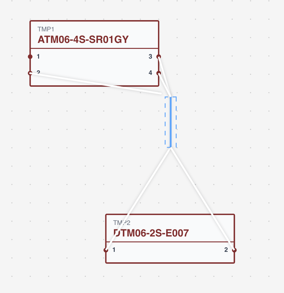
A shielded cable starts as a wire part in the parts library. Two fields make it one:
- Shielded — marks the part as a multicore. Without it the part cannot be used as a shielded cable at all.
- Strands — how many inner conductors it has.
- Strand colours — optionally a colour and stripe per conductor, which are then drawn per strand everywhere.
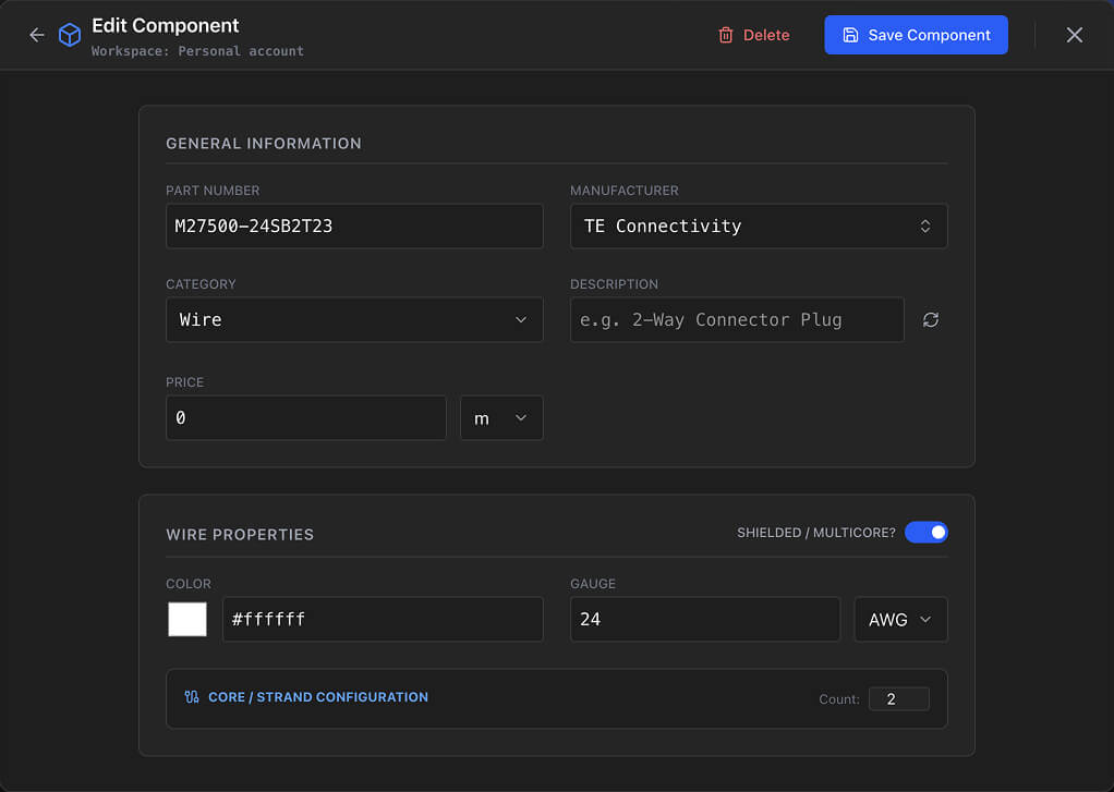
Name shielded parts so the count is visible in a dropdown: "2-Core Shielded 22AWG", "4-Core Shielded 20AWG PTFE".
Configuring the cable
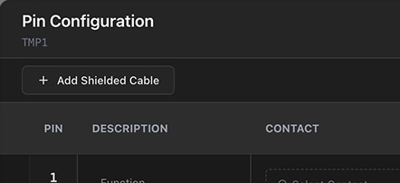
Open Pin Configuration on the connector at one end of the cable and click Add Shielded Cable, then pick the shielded wire part. The configuration dialog opens.
Strand mapping
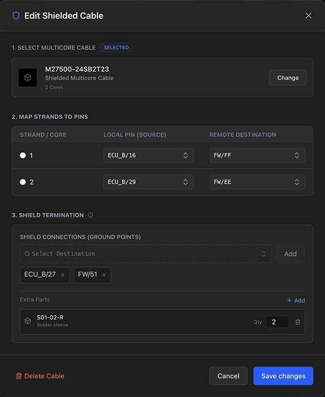
Each inner conductor gets a source and a destination — a component and a cavity at each end. Both are required before the strand becomes a real connection; the strand index sets its order within the cable.
Shield termination
The screen is terminated separately from the conductors. Add a shield connection and choose where it lands — typically a ground ring terminal. You can add more than one, which is how you ground the shield at both ends.
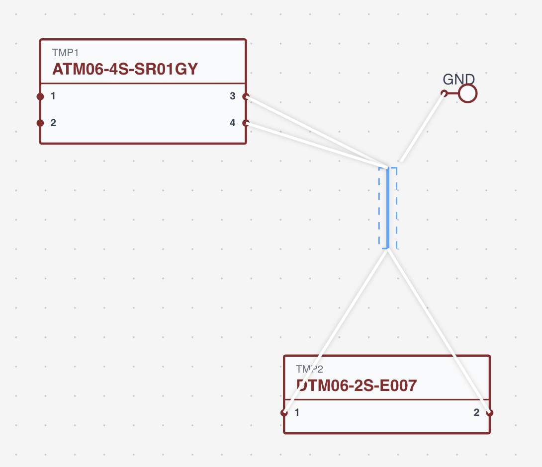
Grounding at one end or both is an EMC decision, not a tooling one. Both are supported; decide which before you map the strands, because it changes how many terminations you need.
Extra parts
Attach the accessories the assembly needs — drain wires, ferrite cores, cable glands, grommets, shield termination lugs — each with a quantity and, where the part is priced by length, a length. They are counted in the BOM.
On the canvases
In the Wiring view each strand is drawn individually between the cavities you mapped it to, and each has its own control points, so you route them exactly as you would any other wire. Shield connections are drawn in a distinct style so they are not mistaken for conductors.
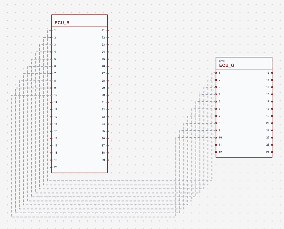
Individual strands can carry colour codes, assigned per row in Pin Configuration exactly like any other wire. See Wire colours and marking.
In the Design view, selecting the cable that carries them shows the cross-section, and hovering or clicking a strand traces that conductor through the harness.
In the derived outputs
BOM
- The shielded wire part itself, with its length taken from the cable in the Design view.
- Contacts assigned to individual strands.
- Seals and plugs for the strand cavities.
- Colour code markers on strands.
- Extra parts — drain wires, ferrites and the rest, at the quantities you entered.
Cut list
- One row per strand, with its source, target, length and cut length.
- Cut length is the base length times the cutlist multiplier from Project settings.
- Shield connections appear as their own entries.
The cable layer editor
Select a cable in the Design view and open Layers from its inspect panel. The layer editor is where you say how the wires are actually packed inside the cable — which conductor sits in which concentric layer, and which way each layer is laid.
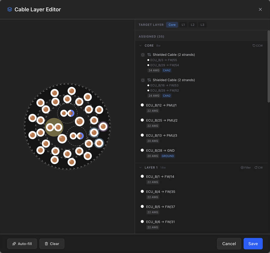
- Cross-section on the left, drawn as concentric rings.
- Wire panel on the right, with a tab per layer and the wires assigned to it.
- Lay direction — clockwise or counterclockwise per layer, set from the layer header or by clicking the chevron ring on the cross-section. The current setting is shown as CW or CCW.
- Filler wires — added to a layer to pack it out where there are not enough conductors to fill it.
The auto-fill button packs the wires across the layers for you, and the clear button empties every assignment so you can start again.
Working well with them
- Decide the termination strategy first. Single-end or both-end grounding changes how many shield connections you add.
- Map every strand before routing. A strand with only one end set is not a connection yet, and will not be routed.
- Add the accessories. Drain wires, lugs and ferrites belong in extra parts, or the BOM understates the assembly.
- Use the description field. Labelling strands "CAN-H", "CAN-L", "Shield Drain" in Pin Configuration makes the export readable on the shop floor.
- Check the design rule checks afterwards. An unterminated shield or an unmapped strand is exactly what they are for.
Related chapters
Where this chapter leads next, and what it assumes you have already read.
Pin configuration
Where the harness is wired — the wire, contact, seal and colour codes on each connector cavity.
Wire colours and marking
Heat shrink colour code bands assigned per cavity, how long each one is, and how the BOM counts them.
BOM and cut list
Two outputs derived from the sheet: how quantities, pricing, multipliers and cut lengths are worked out.