From an empty sheet to a released cutlist
How Wiring Studio models a harness, what it derives from that model, and how each view feeds the bill of materials and the cutlist.
Chapters
Last updated 3 September 2026
Wire colours and marking
Wire identification is done with heat shrink markers. Each connection can carry one or more coloured bands, assigned per cavity, drawn on the wiring diagram in the order they will be applied, and counted in the BOM as real material.
Base colour and colour codes
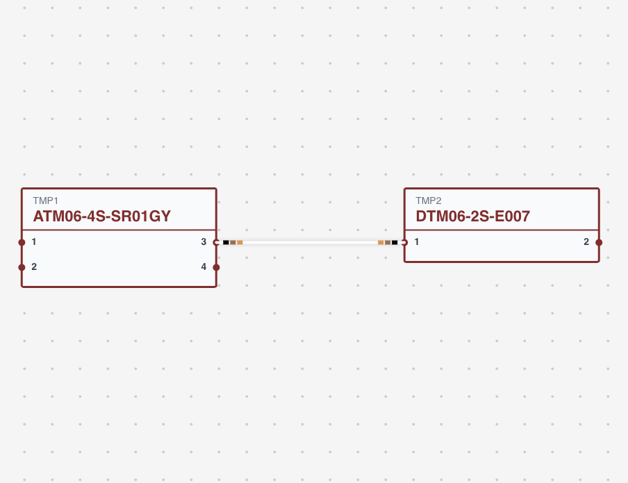
Two different things carry colour here, and it is worth keeping them apart. The base colour is a property of the wire part — its insulation, plus any stripes — and never changes from one project to the next. A colour code is a marker applied to one particular connection, and belongs to that connection alone.
Assigning a colour code
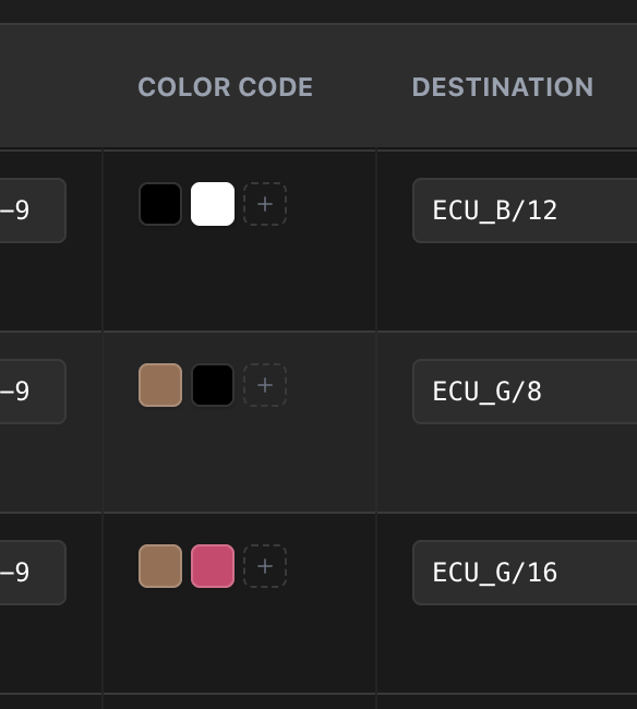
Each part you add is one band, and the order you add them in is the order the bands appear on the wire.
Multi-band codes are what make a harness full of identical black 0.5 mm² wires tractable. A two-band scheme out of eight colours gives 64 distinct identifiers; three bands gives 512.
Heat shrink parts
Markers come from Heat Shrink parts. Each carries a manufacturer, part number, description, a colour, and a price per millimetre — heat shrink is priced by length, like wire and covering.
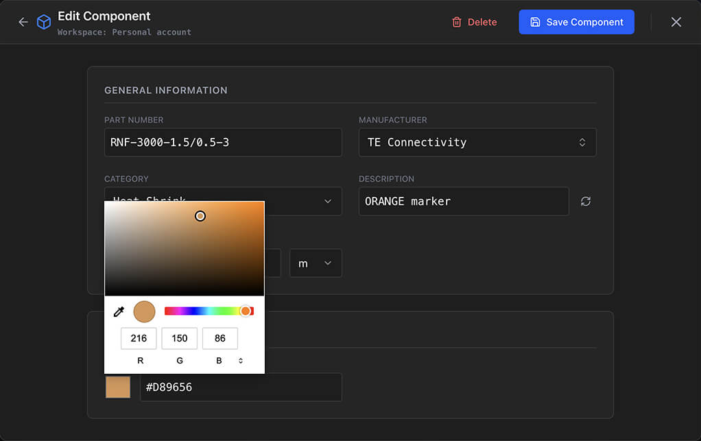
Create one part per colour in your marking scheme. A typical set is red, blue, green, yellow, white, black, orange and brown.
Marker length
Marker Length in Project settings is how long one band is. It defaults to 4 mm, or 0.75 inches in imperial units.
It is the only thing that turns a count of markers into a quantity of material, so set it to whatever your process actually uses. If you cut 6 mm sleeves, put 6 mm here.
How they are drawn
Markers are drawn as coloured bands on the wire in the Wiring view, in the order assigned, using each heat shrink part's own colour. The wire's stroke underneath is its base colour, so the diagram reads the same way the physical wire does — which is the point of drawing them at all.
In the BOM
Heat shrink parts appear in the BOM grouped by part, like everything else. The quantity is the number of connections carrying that marker multiplied by the marker length, shown in the project's units.
So a red marker used on 10 connections with a 4 mm marker length is reported as 40 mm. The Sum column is that quantity times the unit price, and the Total applies the project's price multiplier.
Not to be confused with twisted pair colours
Twisted pair group colours are not colour codes. When you twist wires together the Wiring view gives the group a colour from a ten-colour palette so you can see which wires belong together on screen. It is a diagramming aid — it does not correspond to any heat shrink, appears nowhere in the BOM, and means nothing on the bench.
Working well with them
- Fix the scheme first. Create every heat shrink part before you start marking, so you are not inventing the scheme one cavity at a time.
- Match the physical process. Set the marker length to your real sleeve length, or the BOM quantity is wrong by a constant factor.
- Check before exporting. Look over the bands in the Wiring view before running a PDF export.
- Share the parts. In an organisation the library is shared, which is what keeps everyone marking from the same set of colours.
The design rule checks include a costing category, so a heat shrink part with no price set will be reported rather than quietly costing nothing.
Related chapters
Where this chapter leads next, and what it assumes you have already read.
Pin configuration
Where the harness is wired — the wire, contact, seal and colour codes on each connector cavity.
Cable shielding
Multicore shielded cables: mapping strands to cavities, terminating the shield, and the layer editor.
BOM and cut list
Two outputs derived from the sheet: how quantities, pricing, multipliers and cut lengths are worked out.