From an empty sheet to a released cutlist
How Wiring Studio models a harness, what it derives from that model, and how each view feeds the bill of materials and the cutlist.
Chapters
Last updated 3 September 2026
Drawing the harness
The Design view is the formboard: the canvas where you build the physical layout of the harness. You place components, route cables between them, and set the lengths, coverings and labels that the BOM and cut list are derived from.
Moving around the canvas
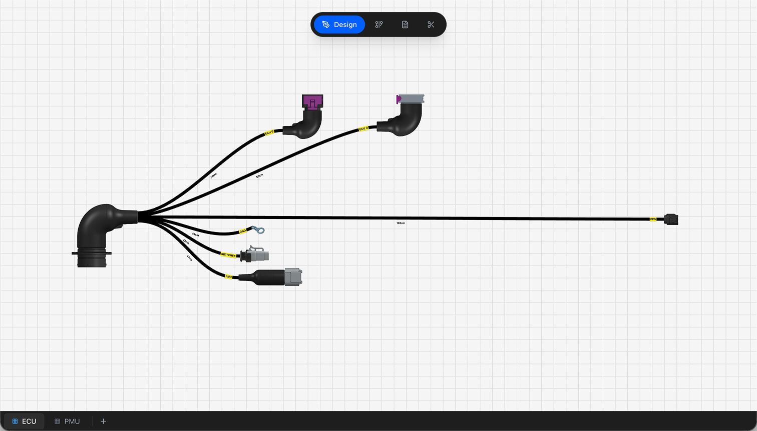
- Pan — drag an empty part of the canvas.
- Zoom — scroll the wheel. The range is 0.1× to 10×, at 1.05× per scroll increment; hold Ctrl to invert the direction.
- Grid — a 40 px reference grid. It is there to line things up by eye; nothing snaps to it.
- Deselect — click an empty area.
- Auto-Scale Layout — scales the whole layout to fit the viewport in one click, from the actions panel or the canvas context menu. Curve shapes, waypoints and tangent handles are preserved.
- Light or dark canvas — the toggle in the corner switches the canvas independently of the rest of the app, and the choice is remembered per view.
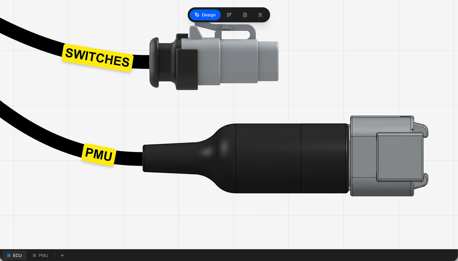
The Design and Wiring canvases keep separate viewports, so switching between them does not lose your place in either.
Selecting
Click a component or a cable to select it. Selecting a component opens its inspect panel; selecting a cable opens the cable panel described below.
Selecting several at once
- Shift-click — add or remove a single component.
- Shift-drag — draw a marquee over an area.
- Cmd/Ctrl + A — select every component on the sheet.
- Escape — clear the selection, or cancel a placement in progress.
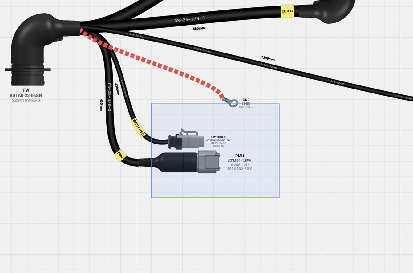
With more than one selected you can drag them as a group, delete them together, or right-click and Save as Component to turn the selection into a reusable component.
Adding components
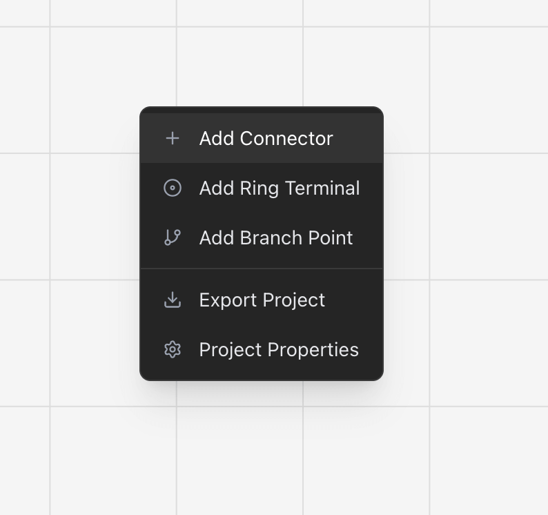
The actions panel on the right places the three components you use most — Connector, Ring Term. and Branch Pt. — by click. Right-clicking the canvas offers the same, plus inserting a saved component and saving the sheet as one.
Component types
- Connector — the main electrical connector, with a cavity count from its library part. The most common component in any harness.
- Ring terminal — a ring-style crimp terminal for a bolt-on connection.
- Branch point — where a cable splits, also called a transition.
- Splice — where conductors are joined. Requires a parent component.
- Diode — anode and cathode pins. Requires a parent component.
- Resistor — two pins. Requires a parent component.
- Custom part — anything the standard categories do not cover.
Splices, diodes and resistors attach to a parent component, which you choose in the component dialog. They are added from the Wiring view canvas menu, where the pin-level context they belong to is visible.
The component dialog
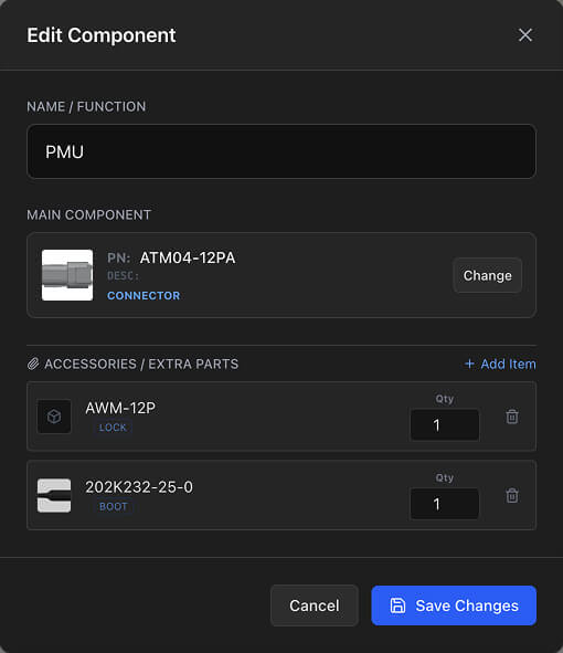
Working with components
Select a component to open its inspect panel. The title is editable in place, and the panel gives you its properties, its pin configuration, its mating connector, and the option to save it as a component or delete it.
| Action | What it does |
|---|---|
| Drag | Moves the component. Nothing snaps to the grid. |
| Flip H / Flip V | Mirrors it left-to-right or top-to-bottom, taking its connection points with it. |
| Duplicate | Copies the component, its part and its extra parts, offset slightly. Rename the copy. |
| Delete | Removes the component together with every cable and wire attached to it. |
Connection points are stored relative to the component's own origin, so cables stay attached correctly when you move or flip it.
Deleting a component deletes the wiring that went to it. It is in the undo history, so Cmd/Ctrl + Z brings it back.
Routing cables
Cables are the physical runs between components. Every wire you assign in pin configuration travels inside one.
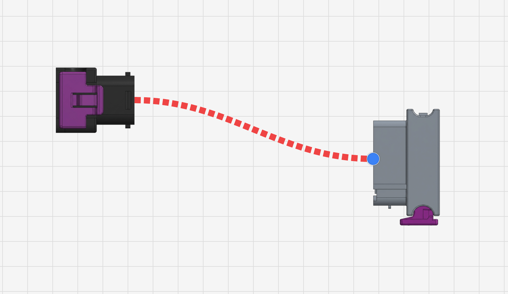
If the snap highlight does not appear, zoom in. Snap range is measured in screen distance, so zooming in widens it in real terms.
Branch points on an existing cable
You do not have to split a cable by hand. Drop the end of a new cable onto an existing one and it splits at that point with a branch point created for you, or right-click a cable and choose Add Branch Point. The original length is divided proportionally between the two new segments.
Shaping a cable
Cables are drawn as smooth curves. Reshape any of them with waypoints and tangent handles.
- Add a waypoint — click the cable at the point you want it.
- Move a waypoint — drag it.
- Remove a waypoint — double-click it.
- Tangent handles — each waypoint has two; drag them to control how the curve enters and leaves that point.
- Reset Curve — right-click the cable to remove every waypoint and return to the default shape.
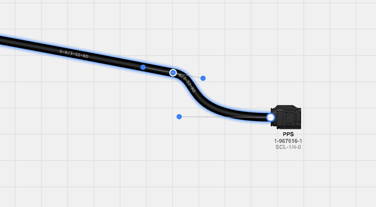
Waypoints are for routing round other components and for producing a drawing someone can read. They do not change the cable's length, which is a value you set.
Cable details
Select a cable and a floating panel opens over the canvas with everything about it.
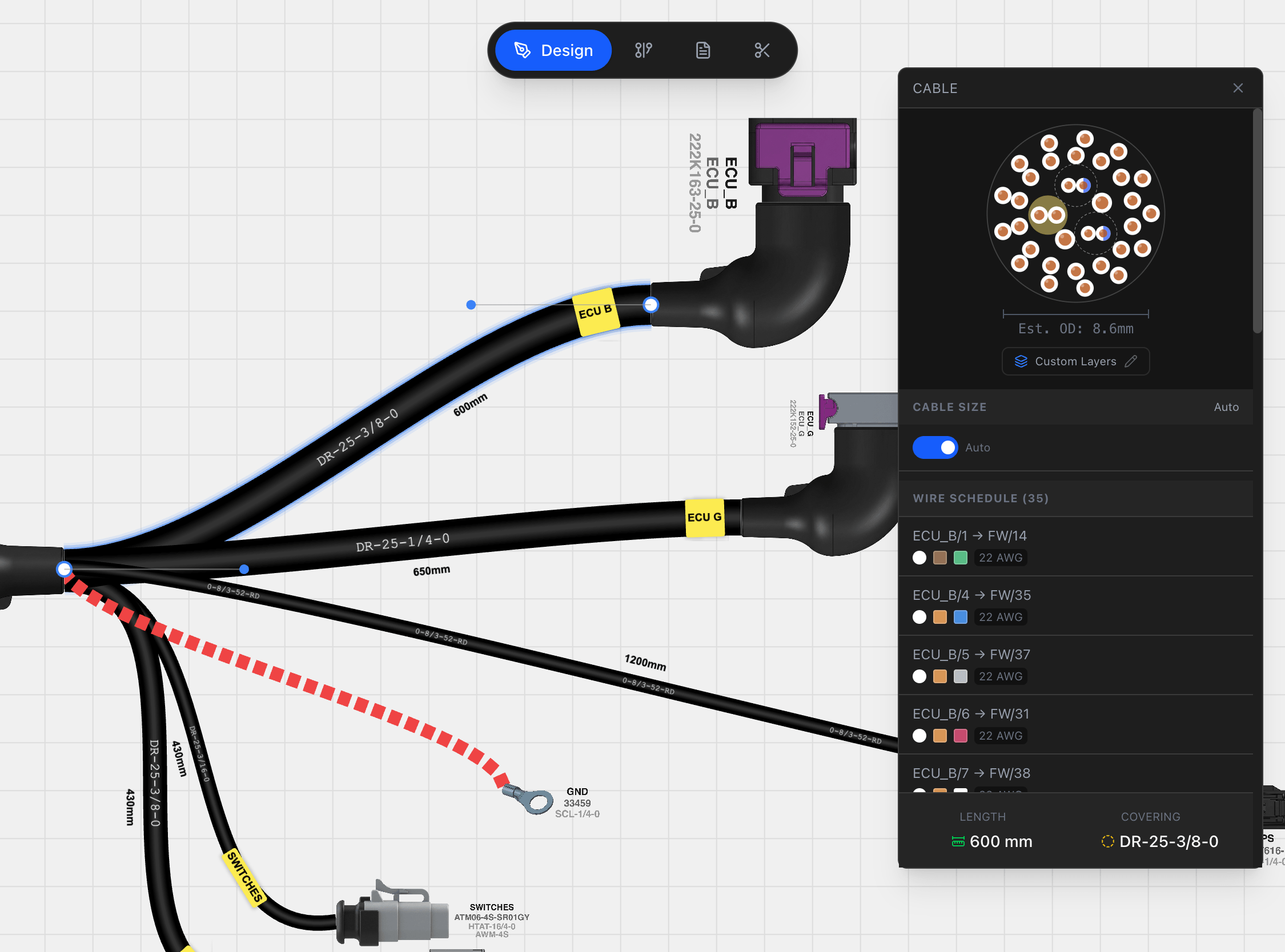
- Cross-section — a drawing of how the wires sit inside the cable. Hover a strand to highlight it, or click to trace it.
- Wire schedule — every wire in the cable with its source, target, colour and gauge, and an indicator for shielded strands.
- Length — editable, in the project's units.
- Covering — a covering part from the library.
- Cable size — automatic from the wire count, or turn Auto off and set the drawn thickness yourself with the slider.
- Layers — opens the cable layer editor for concentric layer assignment.
Cable properties
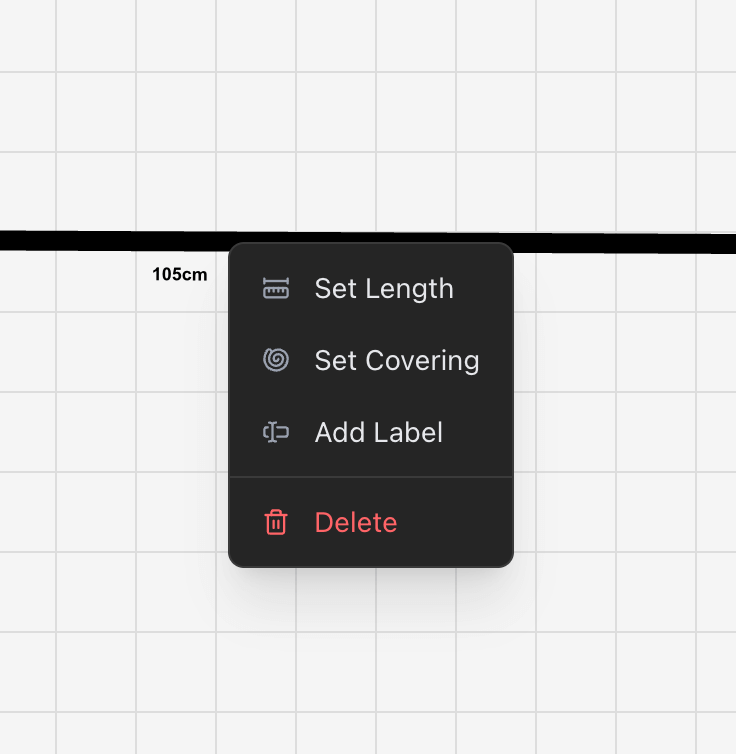
Length is set in the project's units and is stored in centimetres and inches at the same time, so switching units in Project settings never loses precision. Metric shows millimetres or centimetres; imperial shows fractional inches such as 3 1/4 or 7/8. It feeds straight into the cut list.
Covering assigns a sleeve or tubing part, which appears in the BOM with its length matched to the cable's. The covering's part number is drawn on the cable, so you can see at a glance which is which.
Labels attach label parts to the cable, each with its own background and foreground colour and its own position along the run. They are counted in the BOM with their lengths.
Length label draws the cable's length on the canvas. You can slide it along the cable and offset it from the line, and the Length Label Size slider in the actions panel sets the type size for the whole sheet.
Tracing a wire
Hover a strand in a cable's cross-section, or a wire in its schedule, and the whole route that wire takes is lit up across every cable it passes through. Click instead of hovering to pin the trace, and a chip appears at the bottom of the canvas naming the wire and counting the cables it crosses.
If the wire continues to a connector that is mated to one on another sheet, jumping to that mate carries the trace with you, so you can follow one conductor across a whole project. Escape clears a pinned trace.
Component labels
Show Details in the actions panel draws each component's part number beneath it on the canvas.
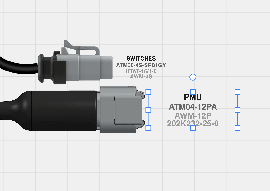
Labels can be dragged, rotated and scaled independently of the component they belong to, and those transforms are saved per component.
Undo and redo
The Design view keeps a full history for the session. Cmd/Ctrl + Z undoes, Cmd/Ctrl + Shift + Z redoes, and the history covers creating and deleting components and cables as well as property changes.
Undo is specific to the Design view. Changes made in the Wiring view and in Pin configuration are applied immediately.
The full list of canvas, view and project shortcuts is in Keyboard shortcuts, and the actions panel keeps the most useful ones on screen under Shortcuts.
Related chapters
Where this chapter leads next, and what it assumes you have already read.
Connections and routing
The schematic: what connects to what, network names, routing, twisted pairs and shielded cables.
Pin configuration
Where the harness is wired — the wire, contact, seal and colour codes on each connector cavity.
BOM and cut list
Two outputs derived from the sheet: how quantities, pricing, multipliers and cut lengths are worked out.