From an empty sheet to a released cutlist
How Wiring Studio models a harness, what it derives from that model, and how each view feeds the bill of materials and the cutlist.
Chapters
Last updated 3 September 2026
Your first harness
This guide takes you from an empty account to a working two-connector harness with wiring, a bill of materials and a cut list. It should take about twenty minutes, and everything it covers has a chapter of its own if you want more detail.
Sign up
Open Wiring Studio and sign up with your email address. No credit card is required — the Free plan includes 3 projects, 1 sheet per project and 5 reusable components, and every drawing, wiring and export feature is available on it. See Pricing and plans for what the paid tiers add.
The same account signs you in to the browser app and the desktop app. Projects are the same on both, so you can start in one and finish in the other.
The Projects page
After signing in you land on the Projects page. The sidebar has two entries: Projects, and Components for the reusable sub-assemblies covered in Reusable components.
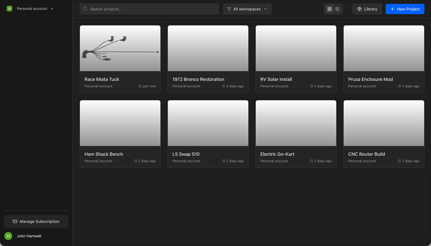
- Grid view — project cards with a canvas thumbnail and the last-modified time.
- Table view — the same projects as a compact list.
- Search — filters by project name.
- Workspace filter — All workspaces, your personal account, or one of your organisations. See Collaboration.
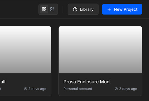
The toolbar also carries Library, which opens the parts library without opening a project, and Import Excel, which is covered in Excel import.
Create a project
Click New Project. Wiring Studio creates the project with a default name and opens the editor. It starts with one sheet and metric units; rename it and change the units later in Project Properties, described in Project settings.
Already documenting this harness in a spreadsheet? Use Excel import instead — drop in the workbook and an agent builds the components, wiring, cables and pin assignments for you.
The project editor
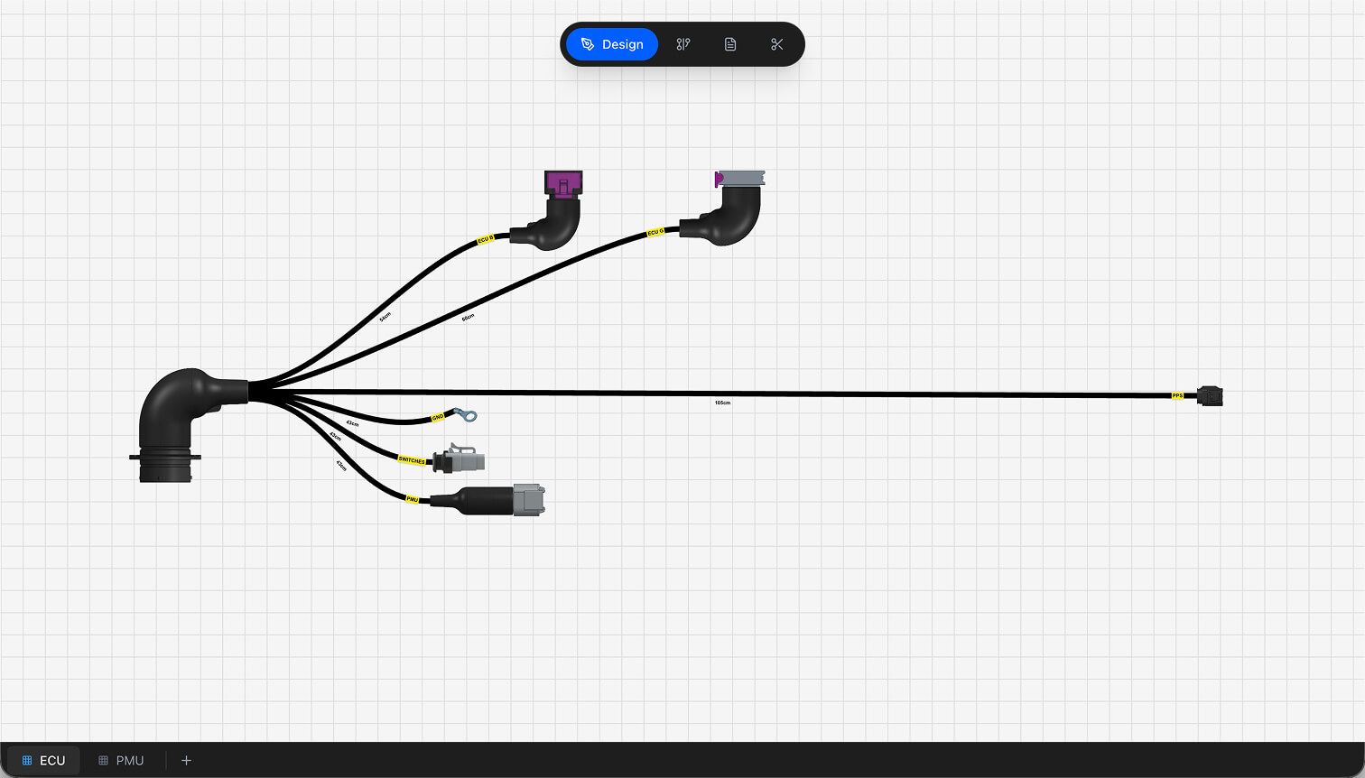
Floating toolbar
The pill at the top centre of the workspace switches between the four views — Design, Wiring, BOM and Cutlist. The active one is highlighted.
Canvas
In Design and Wiring the main area is a pan-and-zoom canvas. Drag an empty area to pan, scroll to zoom, and use the reference grid to line things up. The two canvases keep their own viewport, so switching views does not lose your place.
Actions panel
The panel on the right of the Design canvas holds the things you reach for most: placing a connector, ring terminal or branch point, inserting or saving a reusable component, auto-scaling the layout, and opening export or project properties. It collapses, and stays collapsed.
Sheet bar
The bar along the bottom shows the project's sheets as tabs. Click to switch, double-click to rename, right-click for Rename and Delete, and use + to add one — subject to your plan's sheet limit. See Sheets and workspaces.
Build your first harness
Step 1 — add parts to the library
Everything you place comes from the parts library, so start there. Open Library and add at least a connector and a wire.
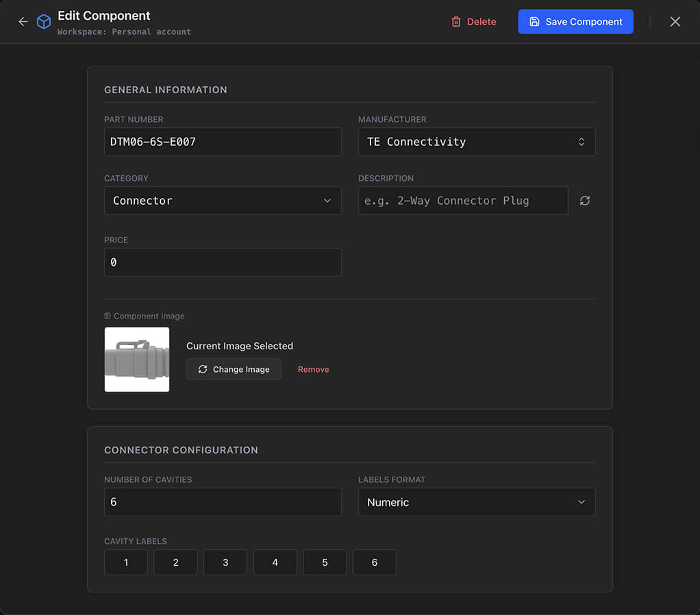
On a paid plan the library can find a part image for you or write the description from the manufacturer and part number. See Parts library.
Step 2 — place two connectors
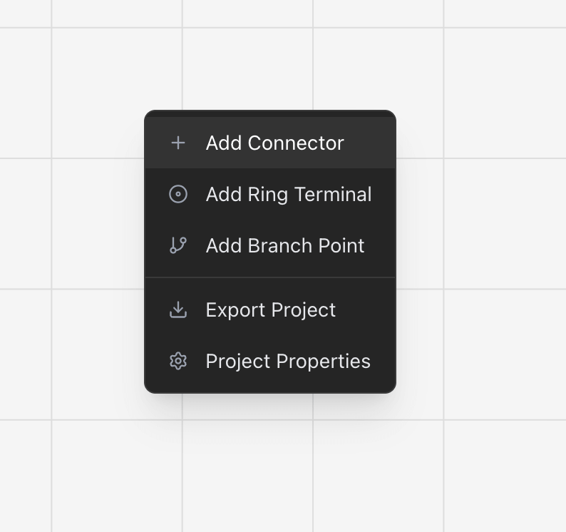
Switch to Design if you are not there already. Place a connector from the actions panel, or right-click the canvas and choose Add Connector.
Step 3 — route a cable
Cables carry the wires between components. Click a connection point on J1 — the small circle on its boundary — and a dashed line follows the cursor. Move to a connection point on J2 and click again to complete it.
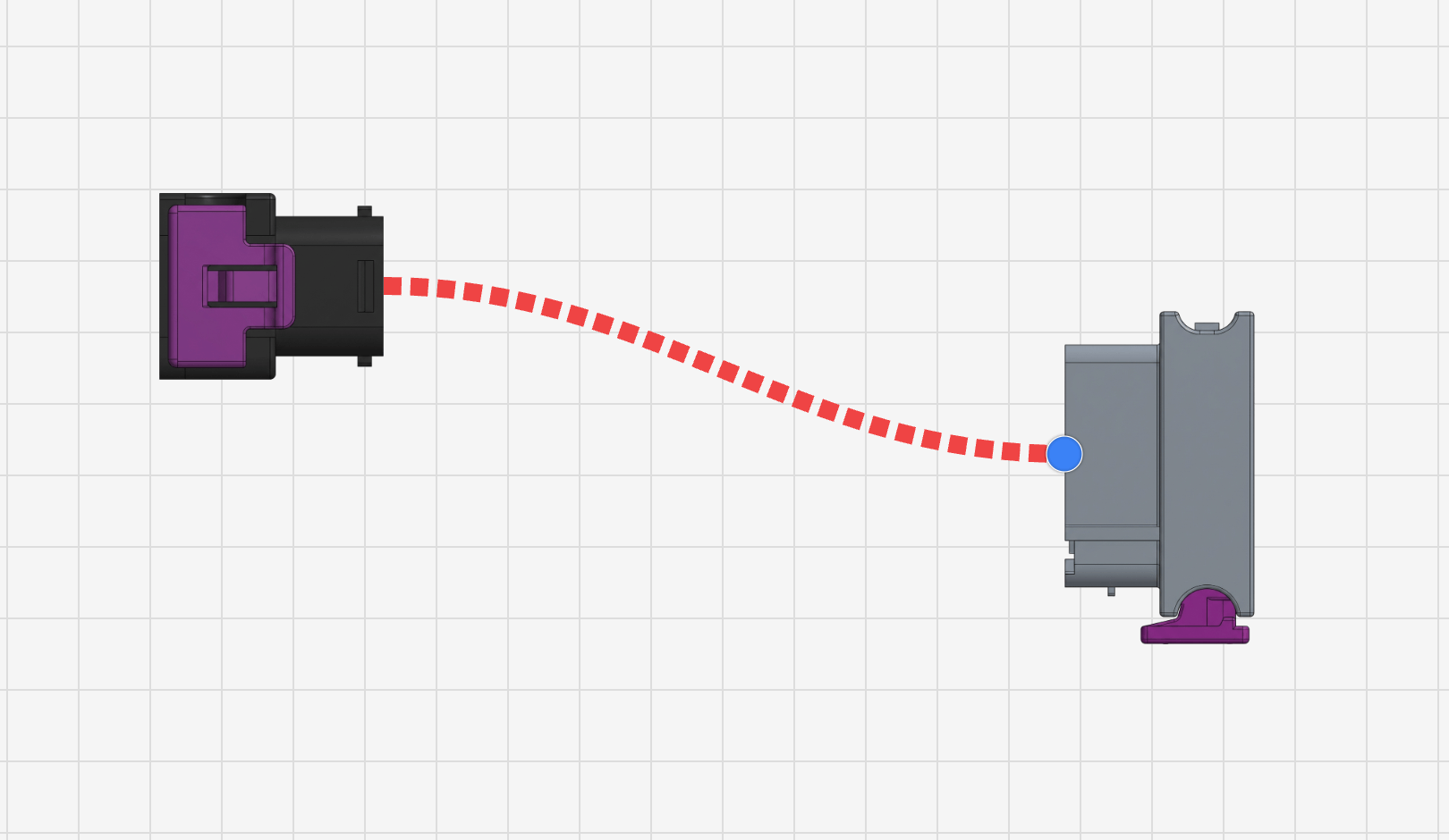
Select the cable to set its Length and Covering, or right-click it for the same plus labels and branch points. The length is what the cut list works from, so it is worth setting now.
Step 4 — configure the pins
Right-click J1 and choose Pin Configuration. The dialog opens beside the canvas, with one row per cavity, and stays open while you work.
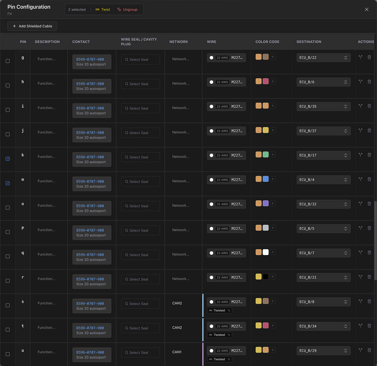
That one table is what drives the Wiring view, the BOM and the cut list. Pin configuration covers double crimps, twisted pairs and shielded cables.
Step 5 — check the wiring
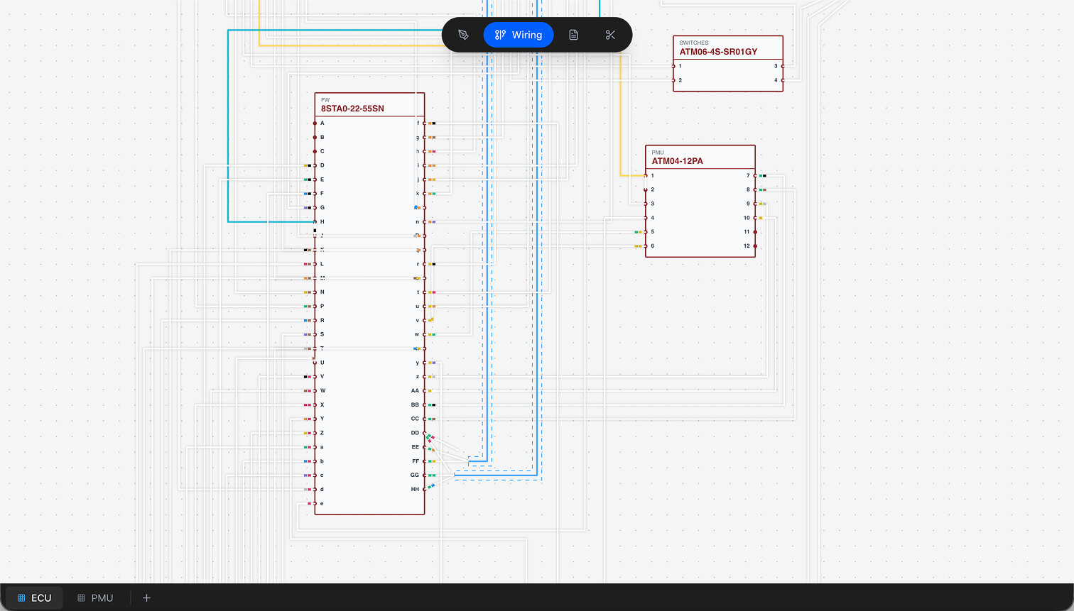
Switch to Wiring. The connections you just made are drawn cavity to cavity. Click a wire to see its details and highlight the network it belongs to, and drag its control points to tidy the path. Right-click the canvas and choose Auto Route to have all of them routed for you.
Step 6 — read the outputs
Switch to BOM. Every part the sheet uses — connectors, wires, contacts, seals, coverings, labels and accessories — is aggregated with quantities, unit prices and totals. Switch to Cutlist for one row per wire with its source, target, length and cut length.
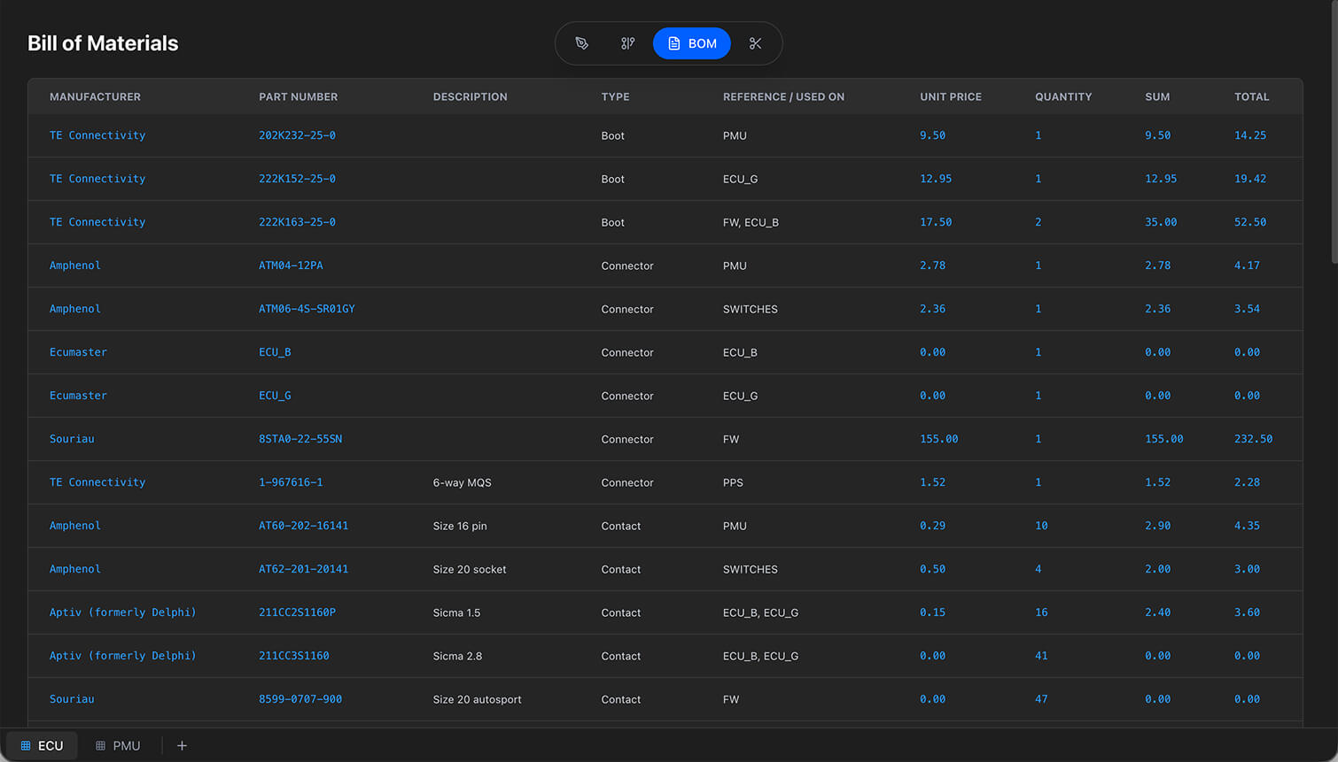
Neither table is editable. Both are derived from the sheet, so if something looks wrong the fix is in Design or Pin Configuration — and the design rule checks will usually have said so already.
Next steps
- Design View — every canvas interaction, component type and cable property.
- Wiring View — networks, auto routing, twisted pairs and pin layouts.
- Parts library — all 16 categories and the fields each one carries.
- Design rule checks — what the badge in the corner is telling you.
- Keyboard shortcuts — the ones worth learning first.
Related chapters
Where this chapter leads next, and what it assumes you have already read.
Drawing the harness
The formboard canvas: placing components, routing and shaping cables, and setting the lengths those carry.
Connections and routing
The schematic: what connects to what, network names, routing, twisted pairs and shielded cables.
BOM and cut list
Two outputs derived from the sheet: how quantities, pricing, multipliers and cut lengths are worked out.