From an empty sheet to a released cutlist
How Wiring Studio models a harness, what it derives from that model, and how each view feeds the bill of materials and the cutlist.
Chapters
Last updated 3 September 2026
Connections and routing
The Wiring view is the schematic. Where the Design view is about where things physically are, this one is about what connects to what: which cavity joins which, through which wire, carrying which colour codes. It renders every connection you make in Pin Configuration and lets you route and tidy each one.
The canvas
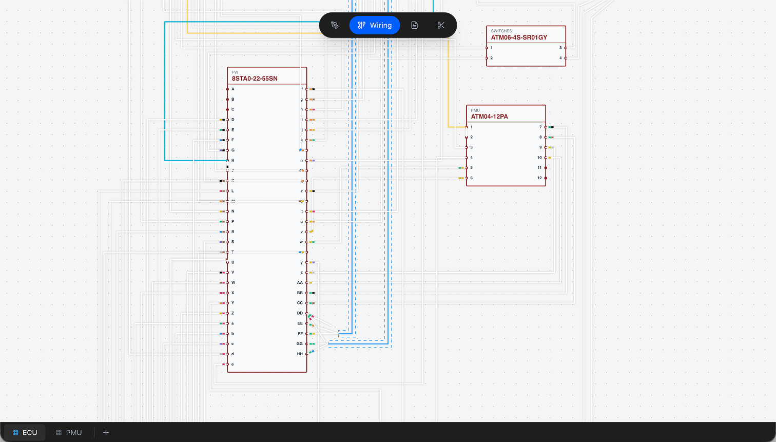
Navigation is the same as the Design view: drag to pan, scroll to zoom between 0.1× and 10×, hold Ctrl to invert the zoom direction, click empty space to deselect. The background grid here is 20 px.
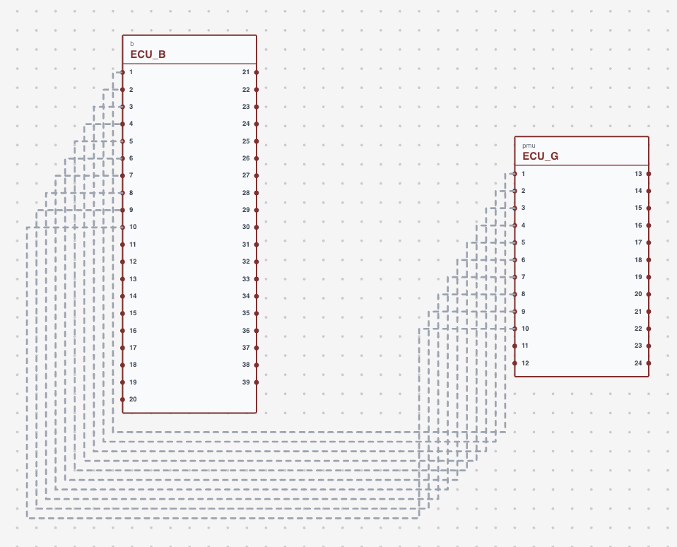
Components are drawn with their cavity labels visible — alphabetic, numeric or custom, according to the connector part's label type in the parts library. Position and rotation come from the Design canvas. Components with no wiring at all are hidden, so the diagram shows only what is actually connected.
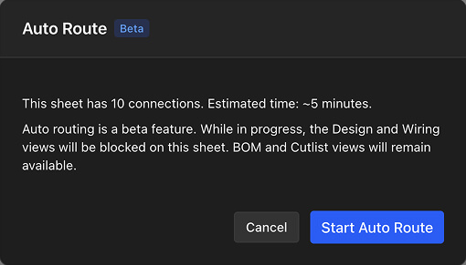
The canvas is blocked while Auto Route is running. An overlay covers it until routing finishes.
Wires and routing
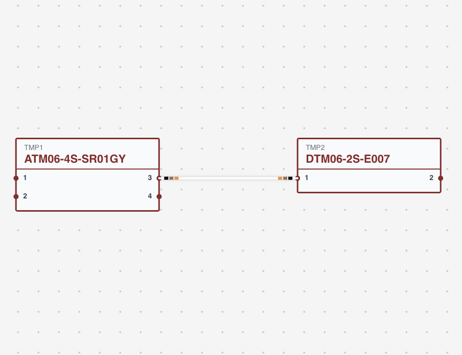
Every wire on this canvas links one source cavity to one target cavity. You create those links in the Pin Configuration dialog, and each one carries:
- Source and target — the component and cavity at each end.
- Wire — the wire part from the library, with its gauge, colour and stripes.
- Colour code — the heat shrink markers on it. See Wire colours and marking.
- Group — its twisted pair, if it is in one.
- Shielded cable — the multicore cable it belongs to, if any.
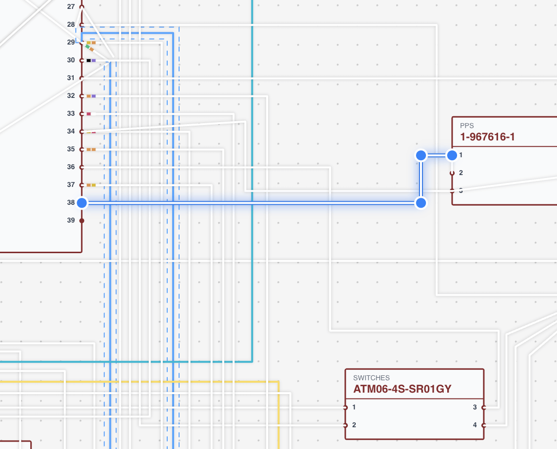
- Control points — the vertices of the path it takes across the canvas.
Adjusting the path
Wire paths are polylines. Drag any control point to move it, right-click a segment to add one, and right-click a point to remove it. Positions are saved as you go.
Auto Route
Right-click the canvas and choose Auto Route to have every wire on the sheet routed at once. It runs on your own machine — an orthogonal pathfinder that keeps wires clear of components and of each other — so it works offline and is available on every plan, including Free.
It replaces the existing control points on every wire it routes, and the whole sheet is one undo step in the Design view's history. Wires you have deliberately shaped by hand will be re-routed too, so run it before the hand-tidying rather than after.
Network names
A network is a connected group of wires — a circuit. Name one and the name spreads to every wire in it, including across connector mates on other sheets, so a signal keeps its name all the way through the project.
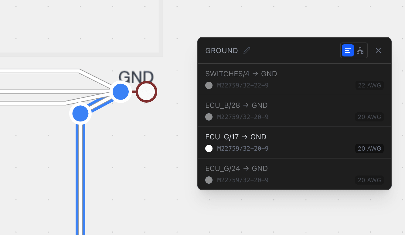
Network names appear in Pin Configuration and in PDF exports. To clear one, empty the field and save.
Because the name propagates across the whole network, rename it from any one wire rather than editing each wire in turn. Editing individually is how a network ends up split into two.
The selection panel
Selecting a wire highlights its entire connected network and dims everything else, which is how you follow a circuit through a dense diagram. The floating panel that opens has two layouts, switched from its header.
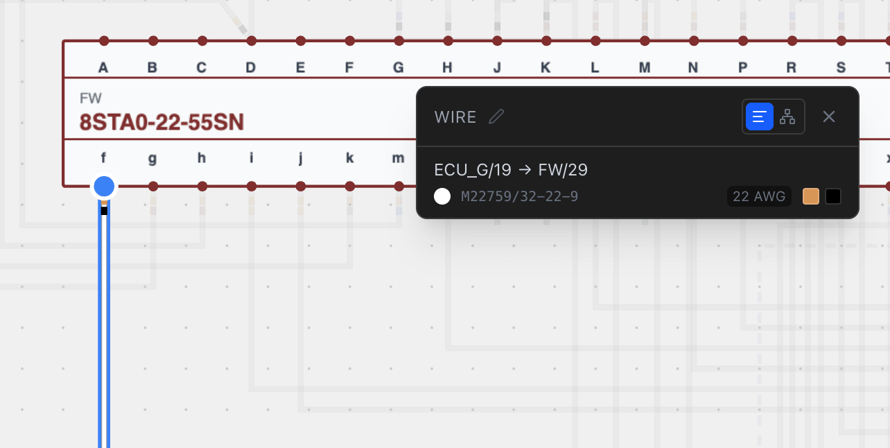
Wire list
- Source and target component and cavity.
- Colour swatches for the base colour, the stripe and each colour-code marker.
- Gauge, in AWG and mm².
- The network name, and the cavity description if one is set.
Connection points
The same wires grouped by connector, pin by pin: cavity index and description, what it connects to, and the wire's colour, colour codes, gauge and part number.
Use the wire list when tracing one conductor across the diagram, and connection points when reviewing everything landing on a single connector.
The panel also counts wires that leave the sheet, so a connection continuing through a mated connector elsewhere in the project is visible rather than looking like a dead end.
Twisted pairs
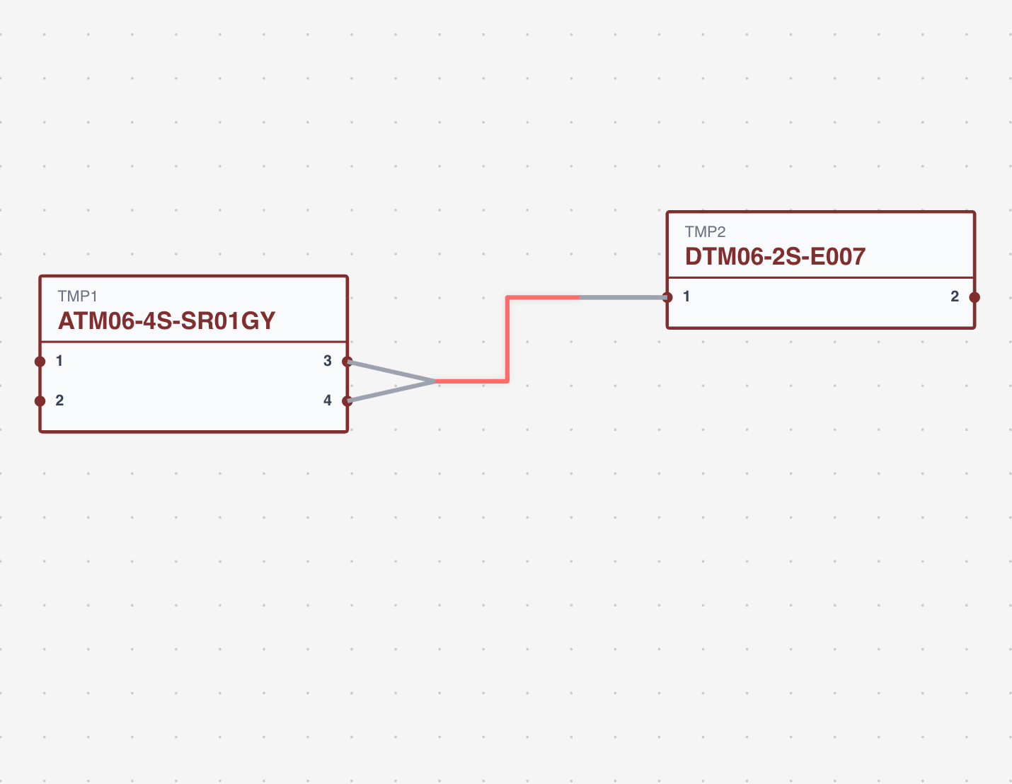
A twisted pair groups two or more wires that are physically twisted together. Select them on the canvas, right-click and choose Twist; the group is created and given a colour from a ten-colour palette so it reads at a glance.
| What you select | What Twist does |
|---|---|
| Wires with no group | Creates a new group containing all of them. |
| One existing group plus loose wires | Adds the loose wires to that group. |
| Wires from several groups | Merges them all into one new group and removes the old ones. |
Ungroup removes the selected wires from their group. If that leaves a group with a single wire, the group is cleaned up automatically.
Twisting can also be done from Pin Configuration, using the row checkboxes and the toolbar that appears with a selection.
Shielded cables
A shielded or multicore cable carries several inner conductors inside a shared shield. The wire part has to be marked as shielded in the parts library, with a strand count, and the cable itself is set up from Add Shielded Cable in Pin Configuration.
On this canvas each strand is drawn and routed individually, and the shield termination is drawn in a distinct style. Control points work exactly as they do on any other wire. Cable shielding is the full walkthrough.
Pin layout
Right-click a connector and choose Pin Layout to set where its pins sit: Left, Right, Top, Bottom, Left-Right or Top-Bottom. It is set per connector and remembered.
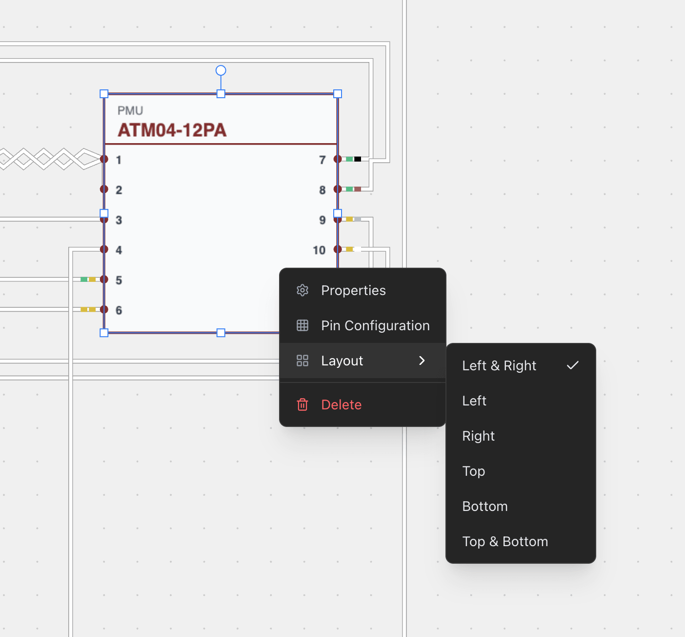
Use it to make the diagram readable — an ECU set to Left-Right with inputs on one side and outputs on the other is far easier to follow than one with everything on a single edge.
How it connects to the rest
- Design view — component positions and cable lengths come from there.
- Pin configuration — wire, contact, seal and colour-code assignments are made there and drawn here.
- BOM — every wire, contact, seal and colour code on this canvas is counted there.
- Cut list — cable lengths from the design plus the connections here produce the cut lengths.
There is no undo in the Wiring view. Control point moves and twist groups are applied immediately; Auto Route is the exception, and lands in the Design view's history as a single step.
Related chapters
Where this chapter leads next, and what it assumes you have already read.
Pin configuration
Where the harness is wired — the wire, contact, seal and colour codes on each connector cavity.
Drawing the harness
The formboard canvas: placing components, routing and shaping cables, and setting the lengths those carry.
Wire colours and marking
Heat shrink colour code bands assigned per cavity, how long each one is, and how the BOM counts them.