From an empty sheet to a released cutlist
How Wiring Studio models a harness, what it derives from that model, and how each view feeds the bill of materials and the cutlist.
Chapters
Last updated 3 September 2026
Pin configuration
Pin Configuration is where the harness is actually wired. Every connector, diode, resistor and splice has one, and what you enter here drives the Wiring view, the BOM and the cut list — there is no separate step that turns it into any of them.
Opening it
Right-click a component on either canvas and choose Pin Configuration, or open it from the component's inspect panel. The dialog opens beside the canvas and does not block it, so you can keep moving things while it is open.
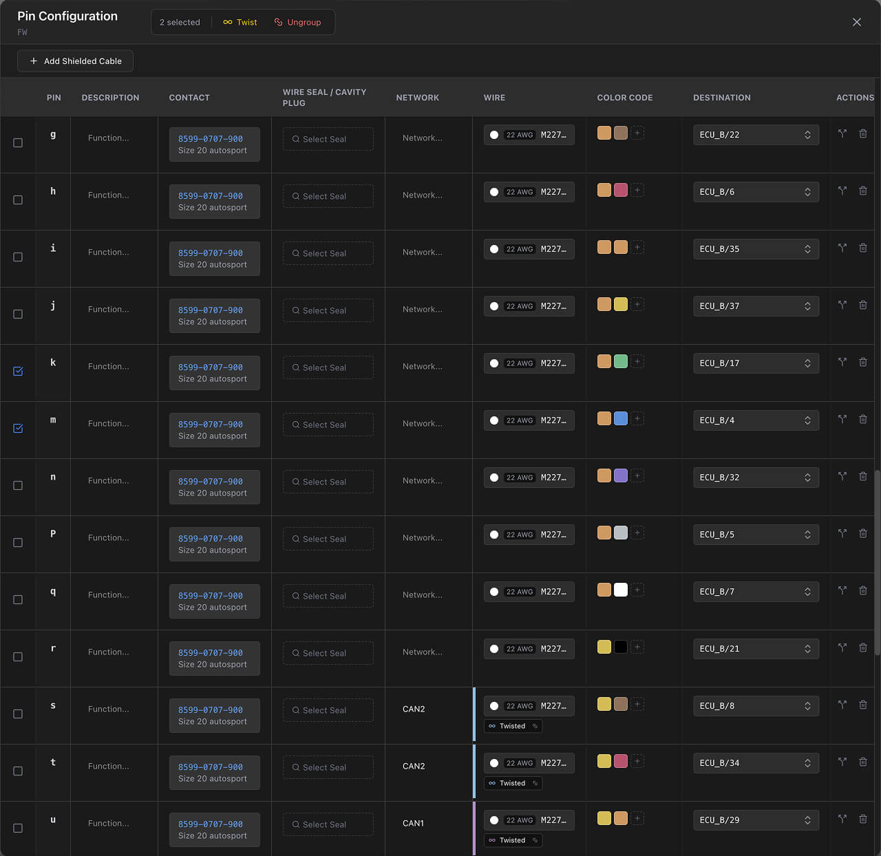
- Connectors — one row per cavity, from the cavity count on the library part.
- Diodes — two rows, Anode and Cathode.
- Resistors — two rows, Pin 1 and Pin 2.
- Splices and branch points — a single row.
If the connector is mated to one on another sheet, a chip in the header says so and takes you straight to that connector's pin configuration. See Sheets and workspaces.
The table
| Column | What it holds |
|---|---|
| Checkbox | Selects rows for the twist and ungroup actions. |
| Pin | The cavity's number or label — alphabetic, numeric or custom. |
| Description | Free text for what the pin is for: "12V Ignition", "CAN-H". |
| Contact | The contact part, validated against the wire's gauge. |
| Wire Seal / Cavity Plug | A seal for a wired cavity, or a plug for one you are leaving empty. |
| Network | The network this connection belongs to. |
| Wire | The wire part: gauge, colour, shielded or not. |
| Color Code | One or more heat shrink marker colours. |
| Destination | The component and cavity at the other end. |
| Actions | Row operations, including adding a second destination. |

Contact arrangement in the toolbar opens the connector's contact arrangement drawing in a docked panel beside the table, so you can check which physical cavity a label refers to without leaving the dialog. A dot on the button means the part has one.
Wiring a cavity
Setting a destination is what creates the connection. It appears immediately in the Wiring view, and the wire, contact, seal and colour-code parts all appear in the BOM.
Fill in Description as you go — Ground, Sensor Signal, 12V Supply. It turns the table into the reference document your assembler actually reads, and it is one of the columns you can include in a PDF export.
Double crimps
One cavity can carry more than one wire — a single contact crimped onto two or more conductors. Use the add button in the Actions column to give a cavity a second destination, and the row expands to show both.
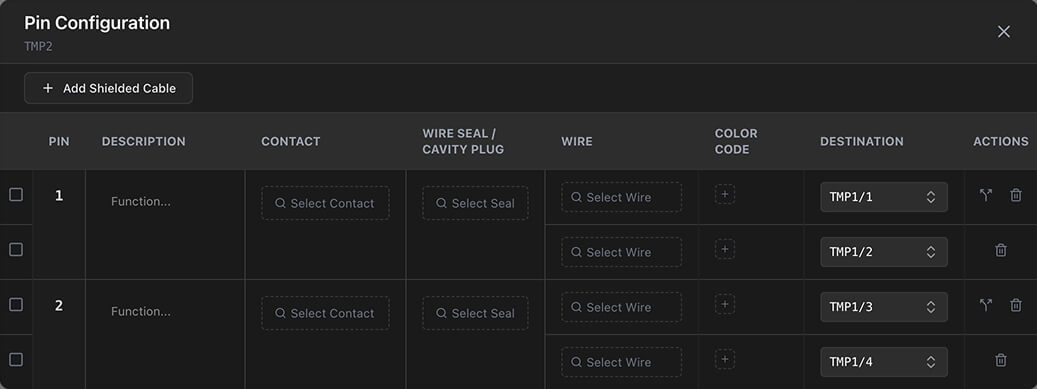
Each destination is its own connection, so both appear in the Wiring view and both get a cut list row. The contact is still one contact and is counted once.
This is common where one pin feeds several downstream branches — power distribution out of a single supply pin, for example.
Twisted pairs
The group takes a colour from a ten-colour palette and is drawn with that indicator in the Wiring view. Ungroup removes the ticked rows from their group, and a group left with one wire is dissolved.
Twisting rows that already belong to different groups merges them into one. The same rules apply here and on the Wiring canvas — they are the same groups.
Shielded cables
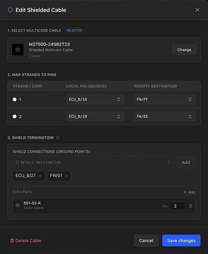
Add Shielded Cable in the toolbar sets up a multicore cable. Choose a wire part that is marked as shielded and has a strand count, and the shielded cable dialog opens.
Strand mapping
Each inner conductor gets a source and a destination — component and cavity at both ends. A strand needs both before it becomes a real connection. The strand index sets its order within the cable.
Shield termination
The shield itself is terminated separately, and you can terminate it more than once — a drain wire to ground at both ends, for example. Each termination is drawn in the Wiring view in its own style.
Extra parts
Attach accessories to the cable assembly — drain wires, ferrites, grommets — each with a quantity and, for length-based parts, a length. They appear in the BOM.
Cable shielding walks through the whole flow.
What changes downstream
- Wiring view — connections, colour codes and twisted pair groups are drawn as soon as you set them.
- BOM — wires, contacts, seals, heat shrink markers and accessories are counted and priced.
- Cut list — each connection becomes a row, taking its length from the cable it runs through in the Design view.
- Design view — a cable's wire schedule and cross-section are built from these assignments.
There is no undo for pin configuration. Changes are applied as you make them — which is also why the design rule checks are worth watching while you work here.
Related chapters
Where this chapter leads next, and what it assumes you have already read.
Connections and routing
The schematic: what connects to what, network names, routing, twisted pairs and shielded cables.
Cable shielding
Multicore shielded cables: mapping strands to cavities, terminating the shield, and the layer editor.
Wire colours and marking
Heat shrink colour code bands assigned per cavity, how long each one is, and how the BOM counts them.