From an empty sheet to a finished cut list
How Wiring Studio models a harness, what it calculates from that model, and how each view feeds the bill of materials and cut list.
Chapters
Last updated 18 September 2026
The harness in 3D
The 3D view shows the current sheet as a physical harness that you can turn and look at from any side. It is built from your Design view layout, with cables drawn as round tubes sized from the wires inside them. Nothing is edited here: change the design, and the 3D view follows.
Opening the 3D view
Click 3D in the floating toolbar, between Wiring and BOM. In the desktop app it is also in the View menu, and Cmd/Ctrl + Alt + 5 switches to it.
The view shows the sheet you have open. Switch sheets from the sheet bar as usual, and it rebuilds for the new one. It uses the Design canvas's light or dark theme, with the same toggle to switch between them.
The 3D view needs WebGL. If your browser or graphics driver has it turned off, the view says so instead of drawing the harness.
What the view shows
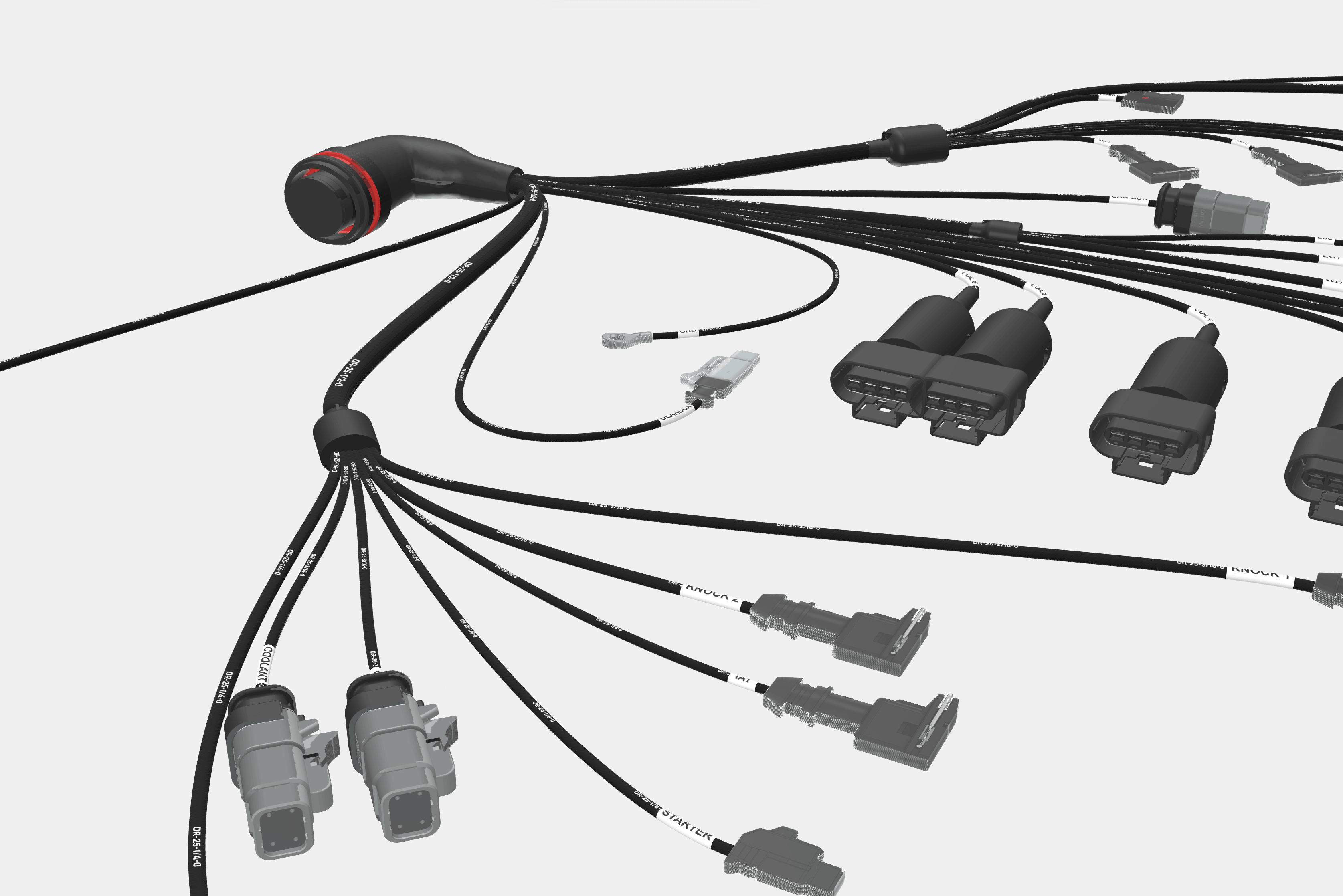
- Components — each part stands where you placed it, as its library image raised into a block. A part with a 3D model shows the model instead, and a part with no image is a plain placeholder block.
- Cables — round tubes that follow the curves you drew. Their thickness is estimated from the gauges of the wires inside, and exaggerated where needed so thin cables stay visible.
- Coverings and labels — a covering's marking repeats along its cable, and each label is a band in its background and text colors.
- Extra parts — backshells, boots and other extra parts sit on their component.
- Branch points — the cables that meet at a transition join in a junction sized to fit them.
- Crossings — where two cables cross, the thinner one arches over the thicker, as it would on a real formboard. Turn this off with Cable hops in the 3D View panel.
Hover over a component to see its name, part number and category. Hover over a cable to see the components it runs between, its covering, its length, how many wires it carries and its estimated outside diameter, in the project's units.
Heights are for looks. Distances across the layout follow your drawing, but a part's height is estimated from its footprint rather than taken from a datasheet, and cable thickness is exaggerated. Take measurements from the Design view and the cut list, not from here.
Moving the camera
| Mouse action | Effect |
|---|---|
| Drag | Orbit around the harness |
| Right-drag, or Shift, Ctrl or Cmd + drag | Pan |
| Scroll wheel | Zoom toward the pointer |
| Middle-drag | Zoom |
The 3D View panel in the bottom-right corner has four camera buttons:
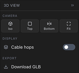
- Iso — an angled view from the front edge of the sheet, where you would stand at a formboard.
- Top — straight down, lined up with the Design canvas.
- Bottom — from underneath, as if you had turned the board over toward you.
- Fit — frames the whole harness again.
In the desktop app, the zoom and Fit to Screen shortcuts work here too. To get the panel out of the way, click the arrow in its header; the small button that replaces it brings it back.
Exporting a GLB file
Click Download GLB in the 3D View panel to save the sheet as a GLB file, the single-file form of glTF. Blender, Windows 3D Viewer and most other 3D software open it, so the harness can go into a render, a slide or a design review without being modeled again.
In the desktop app, Project → Export 3D Model… does the same. It is enabled only while the 3D view is open and the sheet has something on it.
The file holds only the sheet you are looking at, exactly as the view shows it, and is named after the project and the sheet: a sheet called Engine Bay in the project Main Harness saves as Main_Harness_Engine_Bay.glb.
A GLB export is a visual model, not a CAD part. Its size in meters comes from the cable lengths on the sheet, so it is only as true to scale as your layout, and heights and cable thickness are estimated as they are in the view. Don't take measurements from it.
Parts with 3D models
A library part can carry a 3D model file, uploaded in the part editor. See 3D models in the parts library. In the 3D view, the model takes the place of the part's image block.
Model files disagree about units, origin and which way is up, so Wiring Studio doesn't rely on them. Instead it matches the model to the part's image: it tries the model in 24 orientations, keeps the one whose outline best matches the image, stretches it to the image's footprint and colors it from the image. The model then sits exactly where the part sits on the Design canvas, and cables meet it where they meet the image.
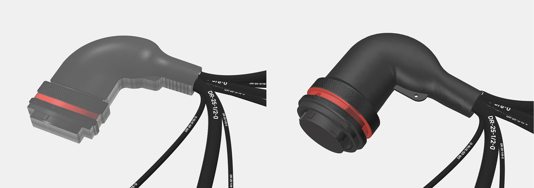
- The part needs an image. Without one there is nothing to match the model to, and the part stays a placeholder block.
- Models load after the rest of the view. Until a model is ready, or when it can't be downloaded, for example offline, the part shows its image block.
Related chapters
Where this chapter leads next, and what it assumes you have already read.
Drawing the harness
The formboard canvas: placing components, routing and shaping cables, and setting cable lengths.
Parts and the library
Sixteen part categories, with the manufacturer data, pricing and properties the BOM and cut list report.
The desktop app
Project tabs, a native menu bar, automatic updates and designing offline, on macOS, Windows and Linux.